
This is a reposting of a blog article and corresponding PDF White Paper that I wrote in April, 2015. Click the following image to view the original PDF White Paper in a popup window.
Problem Statement
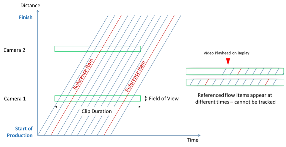
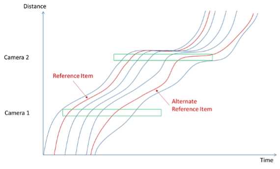
Figure 1 shows a distance-time diagram that depicts a production flow process. Each line represents the trajectory of a single flow item down the production line, from start to finish. The green rectangles represent the activity that can be seen by surveillance cameras focused on the line. Each camera has a field of view (a range of distance) and records action for a specified time (clip duration).
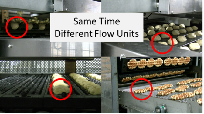
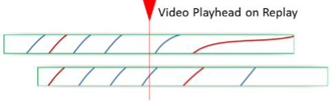
A conventional surveillance system view is shown in Figure 2. Several cameras record simultaneous views of the flow, but the items are different physical objects. On this bakery line, the items circled in red are the different balls of dough that are in the camera’s view at a given point in time.
 |  |
| Figure 2 – Standard Surveillance System View | Figure 3 – Desired Time-Shifted Diagnostic View |
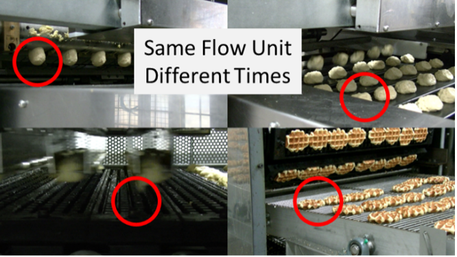
The purpose of this whitepaper is to examine ways to see individual flow items (e.g. specific balls of dough) at ALL processing stages in a time-shifted, side-by-side comparison. This view could offer valuable insights to process engineers and operators. They might see direct cause and effect relationships that would otherwise be invisible or unsuspected … and better understand quality and production.
Currently, there is no accepted way to conveniently make this type of temporal and spatial comparison. This Whitepaper describes such a method.
Time-Shifted Analysis of Flow
The Space-Time diagram allows us to enumerate the different types of flow conditions that are likely to be encountered on the typical production line. The analysis in this section makes the following limiting assumptions:
- Flow units move along a single production path. There are no branches or multiple paths.
- The flow units cannot pass one another.
These conditions apply to a large number of production lines, so even though the analysis in this document applies to a subset of production, the subset is large and important.
Evenly Spaced Flow
The first case involves flow items that maintain a consistent spacing (in distance or time) as they progress along the line. Figure 4 shows the simplest case. Here, flow items maintain strict spacing and they all progress at a steady, constant speed. This is a common production situation where the production line moves in a synchronous manner. Many mass production lines such as automotive assembly lines and food processing lines progress in this rigid manner.
In Figure 5, the flow items maintain the same spacing and order, but the line periodically speeds up and slows down as it moves through different work stations. This may be due to other time-consuming operations such as dough rising towers and heat-treating ovens.
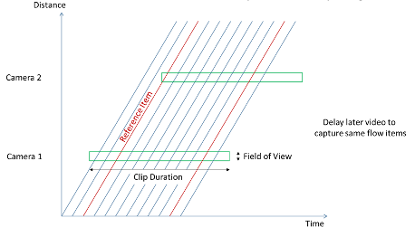
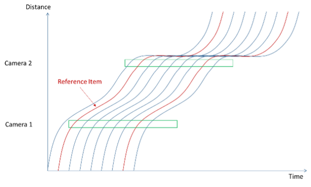
Figure 5 – Variable Velocity & Uniform Spacing
Despite the apparent differences, the constant spacing makes these situations essentially the same for the purposes of building a time-shifted view of a flow unit’s production history. A simple time offset (Figure 6) will align the different video recordings so that the same flow unit is visible in every movie at the same time. In fact, if the offsets are made to align one flow unit, the constant spacing guarantees that all other flow units are similarly aligned.
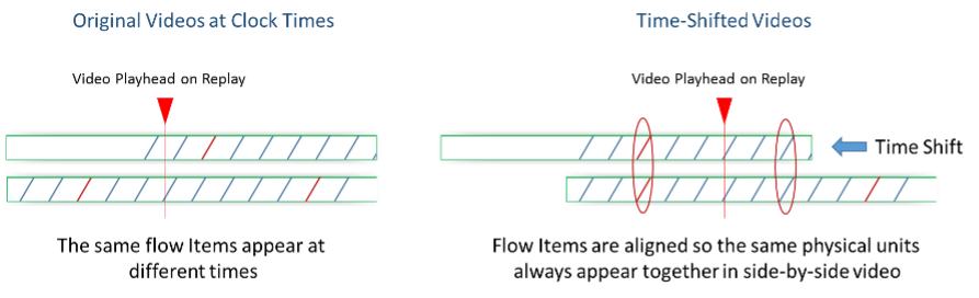
Figure 6 – Time Shifting Aligns Same Flow Units
With this arrangement, it is easy to create a video comparison that juxtaposes the same unit at different locations and times. The time shift will be the flow time that it took for a flow item to reach the next camera location.
Technology
The technical method to achieve alignment is to insert the video clips on different tracks in a multi-track timeline … then slide the videos from downstream cameras back to correspond to videos from the upstream cameras. The offset will be the flow times between the locations that the various cameras are viewing.
Virtually any multi-track non-linear video editor can make the necessary time adjustments. More expensive software can handle more tracks (i.e., more cameras) and offer a variety of special effects. However, since these tools are not designed for this type of comparison, there is generally a steep learning curve to isolate the required tools and techniques from the wealth of other features.
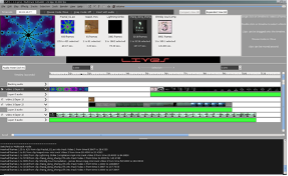 |  |
| Figure 7 – Typical Multi-Track Non-Linear Video Editor | Figure 8 – Dartfish Performance Analysis System |
Figure 7 shows a typical, low cost non-linear video editing package. Figure 8 shows the timeline alignment tool in Dartfish (www.dartfish.com). Dartfish is designed to compare performance-based events in elite athletics. Its toolset closely fits the needs of this problem.
Unevenly Spaced Flow
In many production settings, the flow units flow along the same path and retain the same order (i.e., they do not pass one another), but individual items are not locked into a rigid timing. They can start, stop and progress semi-independently. This situation is shown in Figure 9 and is common for discrete parts manufacturing.
 |  |
| Figure 9 – Variable Velocity and Non-uniform Spacing | Figure 10 – Alignment is More Difficult |
Figure 10 shows how this flow pattern makes it difficult to create the video alignments that are so simple for the case of constant spacing. To handle this variation, we must convert the variable spacing into fixed spacing. Figure 11 illustrates how this might be done. The algorithm is as follows:
- Select a fixed interval that is long enough to capture the longest individually visible action on any recorded clip.
- Extract a clip of that length that is centered on each flow unit at each camera location. The result should be a collection of equal length clips … one collection for each camera location.
- Merge the fixed length clips, in the order of the flow items, into a single video clip … one merged video clip for each camera.
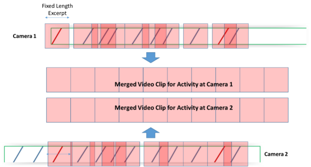
Figure 11 – Extracting Fixed Length Segments for Comparison
Merged clips should be of equal length and the flow units in the merged video clips should appear at roughly the same time and be directly comparable. There are several caveats with this approach. First, it would be a good idea to use several reference units spaced at reasonable intervals to serve as a check on the counting and sequencing assumptions. Second, as the amount of flow variation increases, it may be hard to find an acceptable fixed-length excerpt that capture the actions of all flow items. As the difficulty increases, it may be necessary to switch to the method shown in Figure 12.
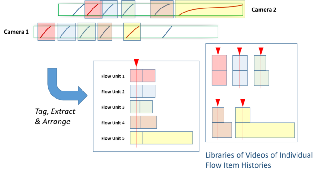
Figure 12 – Tag, Extract & Arrange Library of Flow Item Clips
In Figure 12, it is necessary to extract a video clip for each flow unit as it passes each camera. The length of the extracted video will depend on how long the item remains in the camera’s view. These can be assembled into a linear sequence, or they can be viewed side by side. Either method will collect all of the video for a given flow unit’s production history into a single, compact assembly.
Complex Line Behaviors
Real-world manufacturing processes can be much more complex than the simple, linear flows that were described previously. Two common problems arise as shown in Figure 13. Flow items may take parallel paths through a process step and flow items may be removed from the flow process and discarded (e.g., defects), or they may be pulled and returned out of sequence (e.g. inspections).
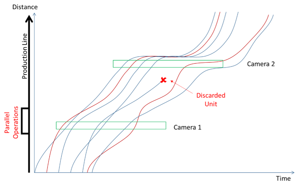
Figure 13 – Complex Situations
Both situations can change the sequence order of the flow items and make it hard to associate video actions at one camera with those of another. The solution is to find a way to visually or electronically identify individual flow items so they can be cross-referenced to the camera video timestamp. If flow items can be reliably associated with their appearances on the various camera feeds, the Tag, Extract and Arrange approach in Figure 12 will still work.
Technology
All of the solutions to uneven flow patterns require some form of video isolation, tagging, extraction and arranging. While there are many software systems that can “slide” video clips on a timeline, the options for this sort of action are very limited. In fact, the author only knows of one software package that has all of the features and capabilities to address this situation efficiently. The software is Dartfish.
The fit between Dartfish and these scenarios is due to its pedigree as a tool to analyze performance in elite athletics. Most athletic skills (hitting a baseball, landing a triple-axel, etc.) are a sequence of actions that build on one another and are practiced repetitively. It is essential to be able to compare performance elements across the repetitions. This is not the same problem as the one we are addressing here, but it demands the same tools. As shown in Figure 14, Dartfish has a tagging panel that can quickly apply “tags” to segments of video while the video is being reviewed. The tagging panel has buttons that can be configured to generate tags in two different ways. In one mode, clicking the button will add a fixed duration tag that is centered at a specific point in the video. This is exactly what is required to identify the fixed length segments in Figure 11. In the other mode, clicking a button starts a variable-duration tag. Clicking the button again denotes the end of the tagged interval. This is the capability needed for the variable duration tagging in Figure 12.
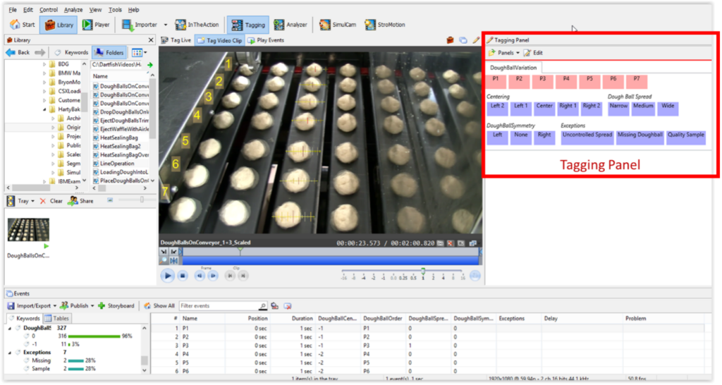
Figure 14 – Dartfish Tagging Panel
Dartfish also has efficient tools to extract the individual tagged segments and reassemble them in new collections or storylines. This completes the functionality that is needed for the Tag, Extract and Arrange processes in Figure 11 and Figure 12.
Finally, Dartfish has the ability to import data from other sources (via CSV) or from live sensors through its System Development Kit (SDK). It is not implausible that a product tracking technology (e.g., RFID) could be connected to Dartfish and some custom software to perform all of the steps in the Tag, Extract and Arrange process automatically. To the author’s knowledge, systems like that do not currently exist, but they would not be very difficult to design and construct.
Application Scenarios
The discussion to this point has been general and theoretical. The scenarios in this section look at specific techniques and methods that might be applied, given camera and software technology that currently available off-the-shelf. Figure 15 shows the basic a linear production line such as one would see in many bakeries. Cameras have been placed a various locations to watch the key transformations as materials flow down the line.
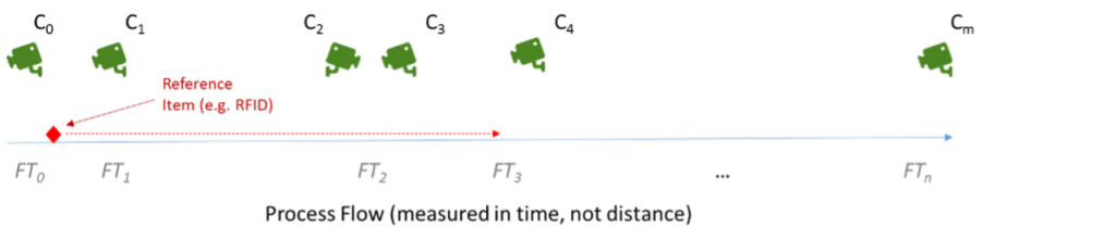
Figure 15 – Time Shifted Video of a Production Line
Application 1 – Ad Hoc Event Chaining and Manual Alignment
The most unstructured situation occurs when there is no opportunity to engineer a formal video recording system. In this scenario, stand-alone cameras are stationed beside the process to capture video clips that roughly cover the flow of the process.
There is no formal item tracking, but it is possible to isolate distinctive flow items or visible events in some of the video clips. The key is to find comparable flow items in each pair of video clips as they progress through clock time.
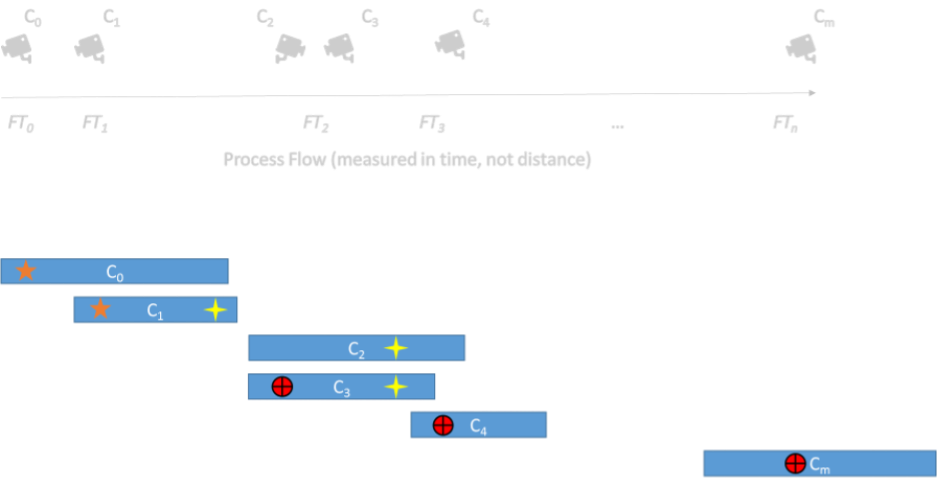
Figure 16 – Video with Variety of Reference Points
In Figure 17, there is no single visible marker or event that is common to all of the clips. However, the clips from Cameras 0 and 1 have an identifiable moment in common. To be useful, the common event must be in the flow units that are moving past the camera. The clips from Cameras 1, 2, and 3 have a different identifiable moment in common. Finally the clips from Cameras 3, 4, and m have a third independent moment that is visible in all three clips.
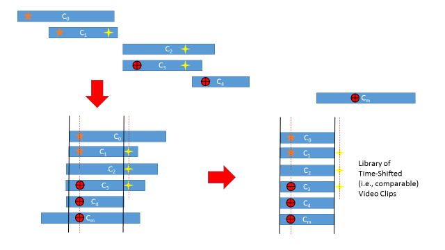
Figure 17 – Chaining Alignment Points and Trimming
With the available information one can take the video clips, place them together on an editing timeline and “slide” the clips relative to one another to make the known common events correspond. This will create a chained sequence where all of the clips show the same set of flow items.
Once the video clips are aligned, they can be trimmed to start and stop at the same point relative to the flow of the reference events. This creates a library of video clips that can be viewed in a synchronized gallery or in any combination to see what happens to a given flow unit at different points of progress along the line.
While this method is manual, it is the most flexible approach when applied to situations where prior planning and synchronization are not feasible.
Application 2 – Marked Flow
In some situations (Figure 18), it may be possible to mark one or more specific flow items as a common point of reference. Some sort of indicator (sticker, dye marker, etc.) would be applied to one flow item as it enters the process. That will supply a consistent reference point in all subsequent video clips.
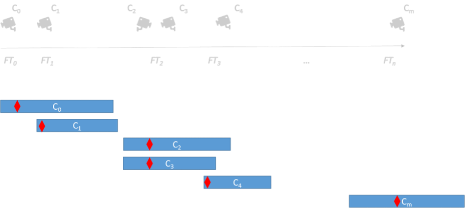
Figure 18 – Video with Common Reference Indicator
With a common indicator, a tool like Dartfish can easily take the different camera video clips and slide them in time relative to one another so the marker appears at the same point in each clip timeline (Figure 19). That single adjustment can be made quite quickly and it will guarantee that all of the flow items are now synchronized across all of the camera streams.
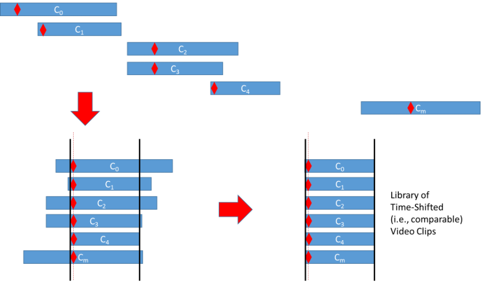
Figure 19 – Alignment On Common Reference Point
This method can be improved by marking multiple flow items at regular spacing. This would create an intrinsic quality check on the accuracy of the alignment.
Application 3 – The “Way Back” Machine
The third application is exciting because it does not require pre-planning. It can be applied to a process after some event has happened. Suppose that several units of product suddenly appear and fail at final inspection. What caused the failures? Was it a problem at one production step or are there some sort of stacking errors that accumulate along the process? These are notoriously difficult problems to diagnose in most production settings. You can’t go back and see what actually happened to the failed units
… or can you?
Most factories have a security surveillance system that records camera feeds on a continuous basis. Current technology can record tens or hundreds of cameras at or near full HD video quality and retain the video for days, weeks or even months. These systems are continuously improving and their costs are steadily falling.
What if the factory extended its existing capability … or acquired a modestly priced system and dedicated it to monitoring the production lines. The cameras in this system would continuously recording all of the process flow, with archives going back days or weeks.
Further suppose that the production process was adjusted so that some visible marker (e.g. red paint on a specific production slot) was placed at strategic points in the moving line. Even better, sensors are added beside the line to register the passage of the moving marked locations.
The result would be the system shown in Figure 20. In this scenario, strategically placed cameras are continuously recording the production flow. When the process owner has a reason to suspect that at problem may be present, the owner can use the data from the registration points to identify the precise segments of video that should be extracted from the surveillance system.
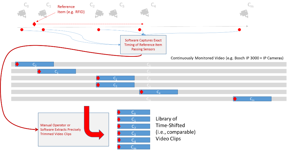
Figure 20 – Construction from Continuous Video Monitoring
These video segments are assembled in a library and process engineers can see what happened to large numbers of flow units … at every stage of production simultaneously. It is intriguing to speculate how many nagging production problems might have been solved much earlier if most factories had a system like this.
Summary
Process engineers and managers now have a way to deeply study the sequential cause and effect relationships that are so common and vexing in mass production manufacturing. The capital cost to apply this approach is very modest (in some cases, nearly zero) and it has very broad applicability.
What it requires is the ability to think about processes and video in a new way. To think about what might be possible if we use the implicit “memory” in video to shift time and space.